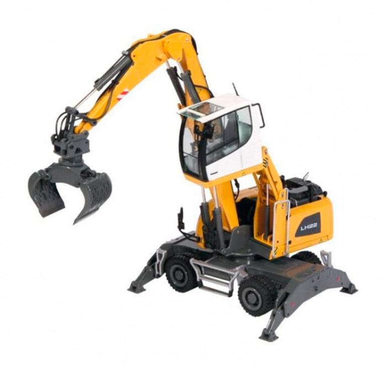
Liebherr has been designing and manufacturing successful machines for material handling for over 50 years. The LH 22 material handler provides high performance and economy. The LH22 is specially designed for use in waste and scrap recycling.
The optimised design of the 105 kW engine supplies a high torque output for high performance. Load peaks are compensated for, to ensure that maximum torque is available at all times for highest handling capacity.
The arrangement of the components in the new upper carriage concept optimises the centre of gravity of the complete machine. This allows greater load capacities while retaining compact dimensions.
The combination of an increased engine output and a higher pump delivery volume guarantees maximum acceleration and speed.
Carefully designed controls guarantee that the hydraulics are optimally configured for the task at hand. Load sensing control ensures that the flow delivered by the pump is optimally distributed when movements overlap. Speed and power are available whenever they are needed.
Optimal harmonisation between the engine and the control valve allows a fast and direct response from the hydraulics to the input command. This is controlled proportionally to enable smooth and gentle movements to be executed when the joystick is moved.
Firm and stable positioning of the machine ensures precise working and maximum handling capacity. The design of the Liebherr undercarriage minimises stress and guarantees maximum stability and durability.

| Liebherr LH22 | 3.0 m | 4.5 m | 6.0 m | 7.5 m | 9.0 m | 10.5 m |
| ||||||||||||||||||||||||
|---|---|---|---|---|---|---|---|---|---|---|---|---|---|---|---|---|---|---|---|---|---|---|---|---|---|---|---|---|---|---|---|---|
| m | Undercarriage |
|
|
|
|
|
|
|
|
|
|
|
|
| m | |||||||||||||||||
| 9 | Stabilizers raised | 4.2* | 4.2* | 3.2 | ||||||||||||||||||||||||||||
| 4 pt. outriggers down | 4.2* | 4.2* | ||||||||||||||||||||||||||||||
| 7.5 | Stabilizers raised | 5.1* | 5.1* | 2.9* | 2.9* | 5.6 | ||||||||||||||||||||||||||
| 4 pt. outriggers down | 5.1* | 5.1* | 2.9* | 2.9* | ||||||||||||||||||||||||||||
| 6 | Stabilizers raised | 5.1* | 5.1* | 3.9 | 4.6* | 2.5* | 2.5* | 6.9 | ||||||||||||||||||||||||
| 4 pt. outriggers down | 5.1* | 5.1* | 4.6* | 4.6* | 2.5* | 2.5* | ||||||||||||||||||||||||||
| 4.5 | Stabilizers raised | 6.7* | 6.7* | 5.7 | 5.8* | 3.8 | 4.8* | 2.6 | 3.3* | 2.4* | 2.4* | 7.6 | ||||||||||||||||||||
| 4 pt. outriggers down | 6.7* | 6.7* | 5.8* | 5.8* | 4.8* | 4.8* | 3.3* | 3.3* | 2.4* | 2.4* | ||||||||||||||||||||||
| 3 | Stabilizers raised | 9.4* | 9.4* | 5.5 | 6.8* | 3.8 | 4.8 | 2.6 | 3.5 | 2.3 | 2.4* | 8 | ||||||||||||||||||||
| 4 pt. outriggers down | 9.4* | 9.4* | 6.8* | 6.8* | 5.2* | 5.2* | 4.3* | 4.3* | 2.4* | 2.4* | ||||||||||||||||||||||
| 1.5 | Stabilizers raised | 9.5 | 10.4* | 5.5 | 7 | 3.8 | 4.8 | 2.5 | 3.4 | 2.2 | 2.5* | 8.1 | ||||||||||||||||||||
| 4 pt. outriggers down | 10.4* | 10.4* | 7.6* | 7.6* | 5.5* | 5.5* | 4.3* | 4.3* | 2.5* | 2.5* | ||||||||||||||||||||||
| 0 | Stabilizers raised | 9.6 | 11.9* | 5.5 | 7.1 | 3.6 | 4.8 | 2.5 | 3.3 | 2.2 | 2.7* | 7.9 | ||||||||||||||||||||
| 4 pt. outriggers down | 11.9* | 11.9* | 7.7* | 7.7* | 5.6* | 5.6* | 4.3* | 4.3* | 2.7* | 2.7* | ||||||||||||||||||||||
| – 1.5 | Stabilizers raised | 9.4 | 12.6* | 5.3 | 7.3 | 3.4 | 4.6 | 2.4 | 3.2* | 7.4 | ||||||||||||||||||||||
| 4 pt. outriggers down | 12.6* | 12.6* | 7.8* | 7.8* | 5.7* | 5.7* | 3.2* | 3.2* | ||||||||||||||||||||||||
| – 3.0 | Stabilizers raised | 9.3 | 13.0* | 5 | 7 | 3.3 | 4.2* | 3 | 3.0* | 6.5 | ||||||||||||||||||||||
| 4 pt. outriggers down | 13.0* | 13.0* | 7.7* | 7.7* | 4.2* | 4.2* | 3.0* | 3.0* | ||||||||||||||||||||||||
Height
| Can be slewed through 360°
| In longitudinal position of undercarriage
| Max. reach
| |||||||||||||||||||||||||||||
| * Limited by hydr. capacity | ||||||||||||||||||||||||||||||||
| The lift capacities on the stick end without attachment are stated in metric tons (t) and are valid on a firm, level supporting surface with blocked oscillating axle. These capacities can be slewed through 360° with the undercarriage in the transverse position. Capacities in the longitudinal position of the undercarriage (+ / – 15°) are specified over the steering axle with the stabilizers raised and over the rigid axle with the stabilizers down. The values apply with the optimum positioning of the two-piece boom. Indicated loads based on the ISO 10567 standard and do not exceed 75 % of tipping or 87 % of hydraulic capacity. The lift capacity of the unit is limited by its stability, the lifting capability of the hydraulic elements, or the maximum permissible lifting capacity of the load hook. In accordance with the harmonised European Standard EN 474-5, hydraulic excavators used for lifting operations must be equipped with pipe fracture safety valves, an overload warning device, a load hook and a lift capacity chart. | ||||||||||||||||||||||||||||||||